Demonstration experiments - see vol. II, §§ 2 and 50.
Simplified instruments - see vol. III, § 49.
Drawings and drawings in lessons - see vol. IV, § 68.
1. Contents: a) The phenomenon of electromagnetic induction. Relationship between the directions of the field, conductor movement and current. Rule right hand. b) Obtaining alternating current by rotating the frame in a magnetic field. The difference between alternating and direct currents, c) A collector, as a device for rectifying alternating current. d) The concept of the design of a dynamo. Reversibility of the dynamo. e) The significance of the discovery of electromagnetic induction and the invention of the dynamo.
2. Methodological notes. To connect with the previous section, at the beginning of studying the topic, the question should be raised approximately in the form in which it arose in M. Faraday. If a conductor carrying current in a magnetic field begins to move, then, in turn, could not the movement of the conductor in the field lead to the emergence of a current? In other words, the question is raised about the possibility of converting mechanical energy into electrical energy.
Methodological difficulties in studying the phenomenon of electromagnetic induction and the principle of the design and operation of a dynamo are caused by the same reasons that were indicated in § 101, 2. However, they are easier to overcome, since similar issues have already been considered in the previous study of the electric motor. In order to simplify the presentation and ensure accessibility of the material for students, it is necessary to resort, in addition to demonstrating experiments, to the widespread use of teaching aids in the form of frames or contours with rings and a manifold (see Vol. II, § 50, 7, Fig. 377, 389 and 390 ), as well as the use of explanatory pictures. When drawing on the board, it is necessary to abandon drawings in an oblique projection and give conventional images in the form of sections similar to that shown in Figure 242. Since students have no idea about electromotive force, in order to simplify the presentation when considering the phenomenon of electromagnetic induction and subsequent issues, it is necessary talk about the electric current induced in conductors, and not about the induced electromotive force, which is with scientific point view is not entirely correct.
Difficulties in studying the phenomenon of induction also arise for the reason that the demonstration galvanometer used in school turns out to be insufficiently sensitive. Therefore, the phenomenon has to be shown in a very complicated form, exciting a current in a coil, and not in a straight conductor.
 It is far from simple to create in students any correct idea of alternating electric current, not only as a current that periodically changes its direction, but also as a continuous change in its magnitude during each half-cycle. It is desirable that students gain an understanding of the graph of alternating current and can give appropriate explanations. This turns out to be possible only if the teacher paid sufficient attention to the construction of all kinds of graphs throughout the course.
3. Electromagnetic induction. The presentation of this issue not only in school, but also in textbooks is unsatisfactory. Due to the methodological imperfection of the equipment, in experiments it is possible to detect only the occurrence of an induction current, but not to substantiate the existing connection between the directions of the field, mechanical movement and the direction of the current.  A detailed description of the experimental methodology, leading to a simplification of the presentation of the question and allowing the introduction of the right-hand rule, as well as a description of the corresponding instruments, are given in Volume II, § 50, 2 and 5. Here, in relation to the experiment, we will limit ourselves to the following instructions:
1) The induction coil usually available in the school must be considered unsuitable from a methodological point of view. A specially made coil should be used, on which the direction of the winding is clearly visible to students and in which the wires are painted in different colors (see Vol. II, Fig. 40).
2) Inside the demonstration galvanometer, if necessary, it is necessary to reconnect the wires leading to its terminals so that the needle deflects according to the current (see Vol. II, § 45, Fig. 323).
3) When demonstrating, use a U-shaped magnet rather than a straight one, since the field pattern of the latter is simpler than that of the former (see Vol. II, Fig. 399 and 401).
 4) You should move the coil by pushing it onto the magnet, but not vice versa. Otherwise, difficulties will arise when introducing the right-hand rule.
Only if the specified conditions are met can the connection expressed by the right-hand rule be established relatively simply experimentally.
The phenomenon of induction is studied in the following form:
1) Induction current occurs when a conductor moves across the field lines, but not along them (Fig. 244).
2) The phenomenon of induction is observed not only during the movement of the coil near the poles of the conductor in relation to the field, but also the field in relation to the conductor, i.e., with the relative movement of the field and the conductor.
3) Four possible cases of conductor movement near the magnetic poles are reduced to two main cases of relative movement of the conductor across the field lines (Fig. 245).
4) The direction of the induction current depending on the directions of the field and displacement is determined by the right-hand rule.
It is advisable to consider Lenz's rule, which is more rational to perform later - when setting up an experiment that detects the resistance of the dynamo armature when it is loaded.
The production of inductions by an electromagnet need not be demonstrated, since this does not introduce anything fundamentally new. A demonstration of the occurrence of current in the secondary coil during interruptions in the current in the primary serves as an introduction to the consideration of the transformer question and should therefore be given at the beginning of the next topic.
When studying the right hand rule, one should, guided by the provisions given in § 101, 3, conduct training sessions with the entire class.
The teacher’s sketches on the board and students’ sketches in notebooks must correspond to all possible cases of movement of the coil relative to the poles (Fig. 244 and 245).

The issue of these drawings is discussed in detail in volume IV, § 68, 1 (Fig. 303-308).
4. Obtaining alternating current by rotating the frame. For the main experiment, which serves to detect the occurrence of alternating current when the frame is rotated in a magnetic field, the coil described in Volume II, § 50, 6 (Fig. 393) is used. Judgment about the change in the direction of the current when the frame passes through the neutral position is made on the basis of the deflection of the needle of the demonstration galvanometer. An explanation for the observed phenomenon is given on the basis of the right-hand rule using a demonstration circuit with rings (Fig. 246 and see Vol. II, Fig. 389) and pre-made pictures similar to Figure 242. In this circuit, as in the study of the movement of a conductor, to simplify the explanation it is necessary to color it individual parts in various colors.
Students should be familiarized with the main differences between alternating current and direct current:
1) Alternating current changes its current at regular intervals. reverse direction.
2) The alternating current strength during such a period of time continuously increases to a certain maximum value and then also decreases to zero.
3) The time during which alternating current flows in both the one and the opposite direction is called the alternating current period. It is advisable to give a graph of alternating current (see Vol. IV, Fig. 306).
In conclusion, we need to consider the structure of a magnetoelectric machine with rings and show its action by heating an electric light bulb (see Vol. II, § 50, 8 and Fig. 394). At the same time, explanations are given for what purpose the armature body is made of iron, and the winding is made of a significant number of turns.
Having mentioned the replacement of magnets with electromagnets, such a machine can be considered as a prototype of modern alternating current machines (alternators) used in technology. It is a misnomer to call alternating current machines dynamos.
5. Rectifying action of the collector. Dynamo. The rectifying effect of the collector is determined using a circuit with a collector and resorting to pre-made drawings such as those shown in Figure 247. Then they demonstrate the operation of a magneto-electric machine with a collector (see Vol. II, Fig. 394), glowing a light bulb and showing with the help of a demonstration galvanometer that the machine produces direct current. It is also useful to talk about the design of a flashlight with a magneto-electric machine (see Vol. II, Fig. 395, II). Having indicated that in technical machines, instead of magnets, electromagnets are used to enhance the action, students are introduced to the dynamoelectric principle, which consists in the fact that the current to power the inductor is taken from the armature of the dynamo, which is its characteristic property.
Students easily see the identity in the devices of a dynamo and a DC motor. Therefore, the question of the reversibility of the dynamo, which is shown experimentally, does not present any difficulties.
6. Dynamo as a converter of mechanical energy into electrical energy. Of fundamental importance is experience showing that the mechanical power consumed by a dynamo depends on the electrical power supplied by the dynamo. This phenomenon is detected by a change in the speed of the falling load, which drives the dynamo (see Vol. II, § 50, 3) when it is under electrical load, compared to idle operation. In connection with this experiment and the phenomenon of reversibility of the dynamo, as stated in Section 3, Lenz's rule should be clarified. Based on a comparison of the rules of the right and left hands and the drawings, it is quite possible to lead students to the conclusion that the inductive current always has such a direction that it creates a force that counteracts the movement produced. Next, the concept of efficiency is introduced. dynamos and its high value is indicated for the most advanced machines. Introduction of efficiency produce, starting from the law of conservation of energy and thereby emphasizing the universality of the latter.
Finally, the significance of the invention of the mechanical generator is considered. electrical energy, which made it possible to obtain strong currents and allowed the widespread use of electrical energy in technology and everyday life.
7. Historical information. Consideration of the significance of the invention of the mechanical generator of electrical energy should be accompanied by relevant historical information. These include: 1) the history of the discovery of electromagnetic induction by M. Faraday; 2) biography of M. Faraday (§§ 9 and 10); 3) brief information about the invention of the dynamo and 4) the history of the discovery of the reversibility of the dynamo. Studying the biography of M. Faraday has a very great educational value.
In addition to the story about Faraday, students should be introduced to the life and most important discoveries of the Russian scientist Emilius Christianovich Lenz, who devoted his entire life mainly to the study of instantaneous-electric phenomena. The most important should be considered his discovery of a law establishing the direction of the induced current (Lenz's rule) and thereby linking into one whole the phenomena of the movement of a conductor in a magnetic field and the phenomena of electromagnetic induction (see Section 6). This discovery was of great fundamental importance and, supplemented by a number of other works by Lenz on electromagnetism, was the first work on the theory of electromagnetic machines that was decisive for world science. Therefore, informing students about Academician Lenz only as the scientist who discovered the Joule-Lenz law is insufficient.
8. Tasks. Problems are used for the same purpose and of the same type as in the topic “conductor movement”. Of particular interest and benefit are the problems-questions about alternating current, which propose to predict how the following will occur: thermal effects, electrolysis of copper sulfate and acidified water, and attraction of iron by an electromagnet (see Vol. II, § 51, 2 and Fig. 406).
9. Tutorials . In addition to the above circuits with rings and a collector, an explanatory picture should be used: “Design of a direct current generator. It is useful to demonstrate transparencies depicting machines (generators) used in technology, direct and alternating currents. It’s even better to show the corresponding fragments from the movie: “Conversion of mechanical energy into electrical energy.”
The demonstration of a working model of a steam power plant makes an exceptionally strong impression on students.
10. Extracurricular activities . As stated in § 49, 3, it is desirable to organize an evening dedicated to M. Faraday, or publish a corresponding wall newspaper. For circle classes, the topic opens up wide opportunities for studying alternating current through a series of experiments (see Vol. II, § 51, 2 and Vol. III, § 2.7).
Topic 3. Magnetic field.
Lecture No. 30.
1. Frame in a magnetic field, electric motors in modern cars.
Eddy currents (Foucault currents), use in cars.
Loop inductance. Self-induction.
Frame in a magnetic field, electric motors in modern cars.
The phenomenon of electromagnetic induction is used to convert mechanical energy into electrical energy. For this purpose, generators are used, the principle of operation of which can be considered using the example of a flat frame rotating in a uniform magnetic field.
Let the frame rotate in a uniform magnetic field ( B = const) uniformly with angular velocity w = const. Magnetic flux coupled to a frame with an area S, at any time t, according to definition, will be equal to
Where a = wt- frame rotation angle at time t(the reference point is chosen so that when t = 0 was a = 0).
When you rotate the frame, a variable will appear in it e.m.f. induction:
![]()
E.m.f. induction changes in time according to a harmonic law.
At sin wt = l e.m.f.
. induction reaches its maximum, i.e. ![]()
Now the expression for e.m.f. induction
can be written in the form ![]()
Conclusion. If a frame rotates uniformly in a uniform magnetic field, then a variable appears in it e.m.f., changing according to a harmonic law.
Notes.
1. From the formula for e.m.f. induction it follows that it is in a straight line
depending on the quantities w, B And S.
2. In Ukraine, a standard current frequency has been adopted n = w/(2p) = 50 Hz, so it's possible
only an increase in the other two greatnesses.
3. To increase IN use powerful permanent magnets or in electromagnets
pass significant current, and also place inside the electromagnet
cores made of materials with high magnetic permeability m.
4. If you rotate not one, but a number of turns connected in series, then
increases S.
5. The process of converting mechanical energy into electrical energy is reversible.
If an electric current is passed through a frame placed in a magnetic lobe, then
a torque will act on it and the frame will begin to rotate. On this
principle based work electric motors designed for
converting electrical energy into mechanical energy.
Electric motors in modern cars.
A frame in a magnetic field is a physical idealization to substantiate the principle of operation of electric motors, which are widely used in the modern automotive industry.
The first thing to point out is the so-called hybrid cars . Their effectiveness involves electric traction at low speeds and the inclusion of internal combustion engines in intense dynamic modes.
So, at low speeds, for example, when driving in urban conditions, the car is driven by an electric DC motor, powered by powerful batteries. When moving to high-speed modes, for example, on suburban highways, there is a switch from the electric motor to traction from the internal combustion engine. Automatically, when the latter is running, the battery is recharged. Thus, hybrid car operates in the recovery mode of spent electrical energy.
Tests hybrid cars showed a significant increase in their efficiency and dynamics in general.
The second direction in creating promising vehicles is the development of the so-called electric vehicles. The latter operate exclusively on traction from DC electric motors and, in the current state of scientific and technological progress, are intended mainly for movement in urban environments over short distances.
Today we are all familiar with household electric generators. Depending on the fuel consumed, purpose and type of engine used, these can be gasoline, gas, diesel and even wind electric generators. These devices have become a part of our lives, and we are used to using them in the countryside and on camping trips, at construction sites and in the garage. Many types of electric generators and electrical appliances do the work for us. Portable hand-held electric generators are built into flashlights, solar panels power remote instruments and sensors, space satellites and mountaineering equipment. But it wasn't always like this. The beginning of the 19th century erupted with a whole series of discoveries related to electricity and magnetism.
After the discovery and study of electromagnetic induction and the calculations carried out, it became obvious that it was possible to create an electric generator that could transform mechanical energy into electrical energy. To obtain current in a closed coil of wire, it is necessary to change the induction flux passing through it. This can be done in two ways: either move the magnet relative to the coil of wire, or move the coil of wire relative to the magnet.
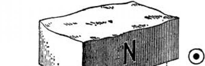
The first homemade magnetic electric current generator, built in 1832, was a very simple installation. Look at his drawing: you see that the EMF in the windings of his coils was excited by the rotation of a horseshoe magnet. The current created by such a machine was not like the current from a galvanic cell - it seemed to rush from side to side, every now and then changing its direction. This current was called alternating current, in contrast to the direct current produced by a galvanic cell.
The installation of another electric generator looked different: a conductor frame rotated between the stationary poles of a magnet. Its ends were connected to two rings on the axis of rotation of the frame, and an electrical circuit was connected to the rings using sliding contacts. At the contacts of the rings, either “plus” or “minus” appeared, which meant the generation of an EMF variable.
The fact that the current was alternating was considered a disadvantage and they began to look for a way to straighten it. To do this, they resorted to the so-called switch. In the second machine, for example, both ends of the frame were connected to a ring, which was cut in half, and each half was insulated with a layer of non-conducting substance. One sliding contact touched only the end of the rotating frame on which there was a “plus”, and the second contact closed on the “minus”. But although the current in the circuit became constant in direction, its magnitude changed with each half-turn of the frame.
To avoid sudden changes in the current value, the number of frames was increased. Their ends were connected to diametrically opposite sections of the cut collector ring of the electric generator. The current from such a magnetic generator is the more similar to a constant one, the more frames there are on the rotating drum - the rotor (the stationary magnets in such a machine are called a stator).
DC and AC electric generators are very similar in design to electric motors. In addition, if you rotate the armature of a DC electric motor, a potential difference appears on its windings - the motor begins to produce electric current, becoming an electric generator. However, for technical reasons, electric current generators are built somewhat differently than electric motors.
Let's take, for example, an AC generator at a large thermal power plant.
Its stator has a winding inside, in which an electric current arises. The rotor is a cylinder with two magnetic poles: north and south. If you magnetize the rotor by passing direct current from an external source into the pole windings, and then begin to rotate it, alternating current will appear in the stator winding.
A separate small DC generator is usually used to excite and operate the rotor. This electric generator is placed directly on the rotor shaft. There is another design option - instead of an exciter generator, a semiconductor current rectifier operates. It takes an insignificant part of the power of the electric generator itself, rectifies the alternating current, and with the resulting current powers the rotor winding.
Our country has adopted an alternating current frequency standard of 50 cycles per second - 50 Hz. This means that within a second the current must flow 50 times in one direction and 50 times in the other. Accordingly, the rotor must make exactly 50 revolutions per second, or 3000 revolutions per minute. Electric generators of thermal stations operate at this speed: they are driven by gas turbine units specially designed for this speed.
This happens as often as in an electric generator in a thermal power plant, where the rotation speed of the gas turbine unit is 3000 rpm. Thus, the frequency of 50 periods is maintained here.
Simple about the complex – Electric generators for electricity production
- Gallery of images, pictures, photographs.
- Electric generators - fundamentals, opportunities, prospects, development.
- Interesting facts, useful information.
- Green News – Electric Generators.
- Links to materials and sources – Electric generators for electricity production.
Generator- a device that converts various types of energy into electrical energy. Generators produce electric current. Examples of generators: galvanic cells, electrostatic machines, solar panels, etc. Depending on the characteristics, various types of generators are used.
For example, using electrostatic machines, you can create a very high voltage, but the current will be very small. And with the help of galvanic cells you can create an acceptable current strength, but they can only work for a short time.
Generator structure
Let's consider an induction electromechanical alternating current generator. There are many generators of this type, but each of them has common basic parts.- Permanent or electromagnet. It creates a magnetic field.
- Winding. An alternating emf is induced in it.
The amplitude of the EMF is induced in each turn of the winding. Since the turns are connected in series, the EMF values will add up. The EMF in the frame will be proportional to the number of turns in the winding. To obtain a large magnetic flux value, a special system of two cores is made in the generators.
In the grooves of one core there are windings that create a magnetic field, and in the grooves of the other, windings in which an emf is induced. One of the cores rotates, it is called a rotor. The second one is stationary and is called a stator. They try to make the gap between the cores as small as possible in order to increase the flux of the magnetic induction vector.
The figure shows a model of a simple generator.

Operating principle of the generator
In the generator, the model of which is shown in the figure, a magnetic field is created by a permanent magnet, and a wire frame rotates inside it. In principle, you can leave the frame stationary and rotate the magnet. From nothing would change.
This is exactly what is done in industrial generators. The electromagnet rotates, and the windings in which the EMF appears remain motionless. This is due to the fact that in order to supply current to the rotor or remove it from the rotor windings, it is necessary to use sliding contacts. Brushes and slip rings are used for this purpose. The current strength that will make the rotor rotate is much less than the one that we remove from the windings.
Therefore, it is more convenient to supply current to the rotor and remove current from the stator. In low-power generators, a rotating permanent magnet is used to create a magnetic field, then it is not necessary to supply current to the rotor at all. And you don't need to use brushes and rings.
When the rotor rotates, an emf appears in the stator windings. This happens because a vortex electric field arises. Modern generators are very large machines. Moreover, with such dimensions (several meters), some of the most important internal parts are manufactured with millimeter precision.
Transformers
Generators that are located at power plants produce a very powerful EMF. In practice, such tension is rarely needed. Therefore, such voltage must be converted.
Devices called transformers are used to convert voltage. Transformers can either increase the voltage or decrease it. There are also stabilizing transformers that do not increase or decrease the voltage.
Consider the transformer design in the following figure.

Transformer symbol: 
Design and operation of the transformer
The transformer consists of two coils with wire windings. These coils are placed on a steel core. The core is not monolithic, but is assembled from thin plates.
One of the windings is called the primary. The alternating voltage that comes from the generator and which needs to be converted is connected to this winding. The other winding is called the secondary winding. A load is connected to it. Load is all the devices and devices that consume energy.
The following figure shows the symbol of the transformer.
picture
The operation of a transformer is based on the phenomenon of electromagnetic induction. When alternating current passes through the primary winding, an alternating magnetic flux is created in the core. And since the core is common, the magnetic flux induces a current in the other coil.
The primary winding of the transformer has N 1 turns, its total induced emf is equal to e 1 = N 1 e, where e is the instantaneous value of the induced emf in all turns. e is the same for all turns of both coils.
The secondary winding has N 2 turns. EMF e 2 = N 2 e is induced in it.
Therefore: e 1 / e 2 = N 1 / N 2.
We neglect the winding resistance. Consequently, the values of induced emf and voltage will be approximately equal in magnitude: |u 1 |≈|e 1 |.
Chapter 5. PRODUCTION, TRANSMISSION AND USE OF ELECTRIC ENERGY
Electrical energy has undeniable advantages over all other types of energy. It can be transmitted by wire over vast distances with relatively low losses and conveniently distributed among consumers. The main thing is that this energy, with the help of fairly simple devices, can be easily converted into any other forms: mechanical, internal (heating of bodies), light energy, etc.
Alternating current, unlike direct current, has the advantage that voltage and current can be converted (transformed) within a very wide range with almost no energy loss. Such transformations are necessary in many electrical and radio engineering devices. But transformation of voltage and current is especially necessary when transmitting electricity over long distances.
§ 37 GENERATION OF ELECTRIC ENERGY
Electric current is generated in generators - devices that convert energy of one kind or another into electrical energy. Generators include galvanic cells, electrostatic machines, thermopiles 1, solar panels, etc. The possibilities of creating fundamentally new types of generators are being explored.
1 Thermopiles use the property of two contacts of dissimilar materials to create an emf due to the temperature difference between the contacts.
For example, so-called fuel cells are being developed, in which the energy released as a result of the reaction of hydrogen with oxygen is directly converted into electricity.
The scope of application of each of the listed types of electricity generators is determined by their characteristics. Thus, electrostatic machines create a high potential difference, but are not capable of creating any significant current in the circuit. Galvanic cells can produce a large current, but their duration of action is short.
The main role in our time is played by electromechanical induction alternating current generators. In these generators, mechanical energy is converted into electrical energy. Their action is based on the phenomenon of electromagnetic induction. Such generators have a relatively simple design and make it possible to obtain large currents at a sufficiently high voltage.
In the future, when talking about generators, we will mean induction electromechanical generators.
Alternator. The principle of operation of an alternating current generator has already been discussed in § 31.
There are many different types of induction generators available today. But they all consist of the same basic parts. This is, firstly, an electromagnet or permanent magnet that creates a magnetic field, and, secondly, a winding in which an alternating EMF is induced (in the considered generator model this is a rotating frame). Since the EMF induced in series-connected turns add up, the amplitude of the induced EMF in the frame is proportional to the number of its turns. It is also proportional to the amplitude of the alternating magnetic flux (Ф m = BS) through each turn (see § 31).
To obtain a large magnetic flux, generators use a special magnetic system consisting of two cores made of electrical steel. Windings that create a magnetic field

are located in the slots of one of the cores, and the windings in which the EMF is induced are in the slots of the other. One of the cores (usually internal) together with the winding rotates around a horizontal or vertical axis. That's why it's called a rotor. The stationary core with winding is called the stator. The gap between the stator and rotor cores is made as small as possible to increase the flux of the magnetic induction vector.
In the generator model shown in Figure 5.1, a wire frame rotates, which is a rotor (without an iron core). The magnetic field is created by a stationary permanent magnet. Of course, you could do the opposite: rotate the magnet and leave the frame motionless.
In large industrial generators, it is the electromagnet, which is the rotor, that rotates, and the windings in which the EMF is induced are placed in the stator base and remain motionless. The fact is that current must be supplied to the rotor or removed from the rotor winding to an external circuit using sliding contacts. To do this, the rotor is equipped with slip rings attached to the ends of its winding (Fig. 5.2). Fixed plates - brushes - are pressed against the rings and connect the rotor winding with the external circuit. The current strength in the windings of the electromagnet that creates the magnetic field is significantly less than the current supplied by the generator to the external circuit. Therefore, it is more convenient to remove the generated current from the stationary windings, and through the sliding contacts to supply a relatively weak current to the rotating electromagnet. This current is generated by a separate direct current generator (exciter) located on the same shaft.
In low-power generators, the magnetic field is created by a rotating permanent magnet. In this case, rings and brushes are not needed at all.
The appearance of EMF in the stationary stator windings is explained by the appearance in them of a vortex electric field generated by a change in the magnetic flux when the rotor rotates.
Lesson content lesson notes supporting frame lesson presentation acceleration methods interactive technologies Practice tasks and exercises self-test workshops, trainings, cases, quests homework discussion questions rhetorical questions from students Illustrations audio, video clips and multimedia photographs, pictures, graphics, tables, diagrams, humor, anecdotes, jokes, comics, parables, sayings, crosswords, quotes Add-ons abstracts articles tricks for the curious cribs textbooks basic and additional dictionary of terms other Improving textbooks and lessonscorrecting errors in the textbook updating a fragment in a textbook, elements of innovation in the lesson, replacing outdated knowledge with new ones Only for teachers perfect lessons calendar plan for a year methodological recommendations discussion programs Integrated LessonsConversion of mechanical energy into electrical energy. The occurrence of a potential difference at the ends of a conductor moving in a magnetic field makes it possible to use this phenomenon to produce electric current. Industrial electricity generators operate on this principle at thermal, nuclear and hydroelectric power plants. In them, the translational movement of the conductors is replaced by a more convenient rotational one.
Where does the energy come from for the separation of charges and the appearance of EMF in the generator? After all, the magnetic field does not do work on moving charges, since the work done by the force is always perpendicular to the velocity vector and is equal to zero. The work of separating charges in the moving conductors of an electromagnetic generator at thermal power plants is performed due to the mechanical energy of steam pressing on the blades of a steam turbine; at hydroelectric power plants this work is performed due to the mechanical energy of water rotating hydraulic turbines that have a common shaft with the generator. In this process, the magnetic field is only an intermediary causing charge separation. It is not the force acting from the magnetic field that plays the role of an external force, but the forces that drive the generator rotor into rotation.
The most powerful electricity generators in the world are manufactured and used in our country.
MHD generator. The most common method of generating electricity at thermal power plants is quite complex. First, the fuel is burned in the furnace of a steam boiler to produce steam. The steam is then directed to the turbine blades and powers it. Finally, the electromechanical generator converts the mechanical energy received from the turbine into electrical energy. At each stage of converting one type of energy into another, significant energy losses occur. As a result, the efficiency of thermal power plants usually does not exceed 35-40%. This means that about 60-65% of coal, oil or gas is burned in furnaces in vain.
Since the efficiency of any heat engine ideally does not exceed
![]()
where is the temperature of the heater, and is the temperature of the refrigerator, then the most important task When developing new methods of energy conversion, the temperature of the working fluid is increased.
A significant increase in the temperature of the working fluid can be achieved in magnetogasdynamic electricity generators, abbreviated as MHD generators.
The design diagram of an MHD generator is shown in Figure 90. In the combustion chamber, when burning oil, kerosene or natural gas, a high temperature (2000-3000 K) is created, at which the gaseous combustion products are ionized, forming electron-ion plasma. To increase the electrical conductivity of the plasma, easily ionizing substances are introduced into the combustion chamber: calcium, sodium, cesium. The hot plasma moves along an expanding channel several meters long, in which its internal

Rice. 90. MHD generator design diagram
the energy turns into kinetic energy and the speed increases to 2000 m/s or more. Like a metal conductor, plasma is generally neutral, but when flying into a region of a strong magnetic field, its constituent particles of different signs are separated under the influence of force, as shown in Figure 90. Electrons, having reached the lower electrode, move in an external circuit along the load resistance to another electrode, where positive ions are neutralized. The power released in the external circuit can be used for various practical needs.
In idle mode, when the external circuit is open between the electrodes, the largest potential difference occurs, equal to the EMF. Depending on the design of the generator, it can reach several hundred or thousand volts.
In an MHD generator, only the plasma is highly heated and there are no moving parts, which, like turbine blades, are simultaneously exposed to high mechanical stresses and high temperatures. The ability to use refractory materials and apply cooling of stationary metal parts in contact with the plasma makes it possible to increase the temperature of the working fluid, and hence the efficiency of the installation. For a plasma temperature equal to input and output, the theoretical efficiency value is approximately 90%. However, in real conditions, the temperature of the exhaust gases at the outlet of the channel is more than 300 K. But if the spent and no longer ionized combustion products are used to produce steam and drive the turbine of a conventional electric machine generator, then the real efficiency of the entire installation will be 50-60%. And this is almost twice the actual efficiency of thermal power plants. Consequently, with the same fuel consumption, MHD generators can produce twice as much electricity.
Another advantage of MHD generators is that they can generate full power, measured in hundreds of millions of watts, within just a few seconds of startup. Therefore, it is advantageous to use MHD generators as backup sources of electricity in case of a sharp increase in energy consumption in power systems.
High efficiency, simplicity of design, small dimensions of MHD generators with high power allow us to hope that once their main drawback - the relatively short service life caused by wear of the nozzle walls - is overcome, they will begin to be widely used to generate electricity on an industrial scale.
The first pilot industrial power plant with an MHD generator with a capacity of 25,000,000 W was launched in our country in 1971.
Today we are all familiar with household electric generators. Depending on the fuel consumed, purpose and type of engine used, these can be gasoline, gas, diesel and even wind electric generators. These devices have become a part of our lives, and we are used to using them in the countryside and on camping trips, at construction sites and in the garage. Many types of electric generators and electrical appliances do the work for us. Portable hand-held electric generators are built into flashlights, solar panels power remote instruments and sensors, space satellites and mountaineering equipment. But it wasn't always like this. The beginning of the 19th century erupted with a whole series of discoveries related to electricity and magnetism.
After the discovery and study of electromagnetic induction and the calculations carried out, it became obvious that it was possible to create an electric generator that could convert mechanical energy into electrical energy. To obtain current in a closed coil of wire, it is necessary to change the induction flux passing through it. This can be done in two ways: either move the magnet relative to the coil of wire, or move the coil of wire relative to the magnet.
The first homemade magnetic electric current generator, built in 1832, was a very simple installation. Look at his drawing: you see that the EMF in the windings of his coils was excited by the rotation of a horseshoe magnet. The current created by such a machine was not like the current from a galvanic cell - it seemed to rush from side to side, every now and then changing its direction. This current was called alternating current, in contrast to the direct current produced by a galvanic cell.
The installation of another electric generator looked different: a conductor frame rotated between the stationary poles of a magnet. Its ends were connected to two rings on the axis of rotation of the frame, and an electrical circuit was connected to the rings using sliding contacts. At the contacts of the rings, either “plus” or “minus” appeared, which meant the generation of an EMF variable.
The fact that the current was alternating was considered a disadvantage and they began to look for a way to straighten it. To do this, they resorted to the so-called switch. In the second machine, for example, both ends of the frame were connected to a ring, which was cut in half, and each half was insulated with a layer of non-conducting substance. One sliding contact touched only the end of the rotating frame on which there was a “plus”, and the second contact closed on the “minus”. But although the current in the circuit became constant in direction, its magnitude changed with each half-turn of the frame.
To avoid sudden changes in the current value, the number of frames was increased. Their ends were connected to diametrically opposite sections of the cut collector ring of the electric generator. The current from such a magnetic generator is the more similar to a constant one, the more frames there are on the rotating drum - the rotor (the stationary magnets in such a machine are called a stator).
DC and AC electric generators are very similar in design to electric motors. In addition, if you rotate the armature of a DC electric motor, a potential difference appears on its windings - the motor begins to produce electric current, becoming an electric generator. However, for technical reasons, electric current generators are built somewhat differently than electric motors.
Let's take, for example, an AC generator at a large thermal power plant.
Its stator has a winding inside, in which an electric current arises. The rotor is a cylinder with two magnetic poles: north and south. If you magnetize the rotor by passing direct current from an external source into the pole windings, and then begin to rotate it, alternating current will appear in the stator winding.
A separate small DC generator is usually used to excite and operate the rotor. This electric generator is placed directly on the rotor shaft. There is another design option - instead of an exciter generator, a semiconductor current rectifier operates. It takes an insignificant part of the power of the electric generator itself, rectifies the alternating current, and with the resulting current powers the rotor winding.
Our country has adopted an alternating current frequency standard of 50 cycles per second - 50 Hz. This means that within a second the current must flow 50 times in one direction and 50 times in the other. Accordingly, the rotor must make exactly 50 revolutions per second, or 3000 revolutions per minute. Electric generators of thermal stations operate at this speed: they are driven by gas turbine units specially designed for this speed.
This happens as often as in an electric generator in a thermal power plant, where the rotation speed of the gas turbine unit is 3000 rpm. Thus, the frequency of 50 periods is maintained here.
Simple about the complex – Electric generators for electricity production
- Gallery of images, pictures, photographs.
- Electric generators - fundamentals, opportunities, prospects, development.
- Interesting facts, useful information.
- Green News – Electric Generators.
- Links to materials and sources – Electric generators for electricity production.
>> Electrical energy generation
Chapter 5. PRODUCTION, TRANSMISSION AND USE OF ELECTRIC ENERGY
Electrical energy has undeniable advantages over all other types of energy. It can be transmitted by wire over vast distances with relatively low losses and conveniently distributed among consumers. The main thing is that this energy, with the help of fairly simple devices, can be easily converted into any other forms: mechanical, internal (heating of bodies), light energy, etc.
Alternating current, unlike direct current, has the advantage that voltage and current can be converted (transformed) within a very wide range with almost no energy loss. Such transformations are necessary in many electrical and radio engineering devices. But transformation of voltage and current is especially necessary when transmitting electricity over long distances.
§ 37 GENERATION OF ELECTRIC ENERGY
Electric current is generated in generators - devices that convert energy of one kind or another into electrical energy. Generators include galvanic cells, electrostatic machines, thermopiles 1, solar panels, etc. The possibilities of creating fundamentally new types of generators are being explored.
1 Thermopiles use the property of two contacts of dissimilar materials to create an emf due to the temperature difference between the contacts.
For example, so-called fuel cells are being developed, in which the energy released as a result of the reaction of hydrogen with oxygen is directly converted into electricity.
The scope of application of each of the listed types of electricity generators is determined by their characteristics. Thus, electrostatic machines create a high potential difference, but are not able to create any significant current in the circuit. Galvanic cells can produce a large current, but their duration of action is short.
The main role in our time is played by electromechanical induction alternating current generators. In these generators, mechanical energy is converted into electrical energy. Their action is based on the phenomenon of electromagnetic induction. Such generators have a relatively simple design and make it possible to obtain large currents at a sufficiently high voltage.
In the future, when talking about generators, we will mean induction electromechanical generators.
Alternator. The principle of operation of an alternating current generator has already been discussed in § 31.
There are many different types of induction generators available today. But they all consist of the same basic parts. This is, firstly, an electromagnet or permanent magnet that creates a magnetic field, and, secondly, a winding in which an alternating emf is induced (in the considered generator model this is a rotating frame). Since the EMF induced in series-connected turns add up, the amplitude of the induced EMF in the frame is proportional to the number of its turns. It is also proportional to the amplitude of the alternating magnetic flux (Ф m = BS) through each turn (see § 31).
To obtain a large magnetic flux, generators use a special magnetic system consisting of two cores made of electrical steel. Windings that create a magnetic field
are located in the slots of one of the cores, and the windings in which the EMF is induced are in the slots of the other. One of the cores (usually internal) together with the winding rotates around a horizontal or vertical axis. That's why it's called a rotor. The stationary core with winding is called the stator. The gap between the stator and rotor cores is made as small as possible to increase the flux of the magnetic induction vector.
In the generator model shown in Figure 5.1, a wire frame rotates, which is a rotor (without an iron core). The magnetic field is created by a stationary permanent magnet. Of course, you could do the opposite: rotate the magnet and leave the frame motionless.
In large industrial generators, it is the electromagnet, which is the rotor, that rotates, and the windings in which the EMF is induced are placed in the stator base and remain motionless. The fact is that current must be supplied to the rotor or removed from the rotor winding to an external circuit using sliding contacts. To do this, the rotor is equipped with slip rings attached to the ends of its winding (Fig. 5.2). Fixed plates - brushes - are pressed against the rings and connect the rotor winding with the external circuit. The current strength in the windings of the electromagnet that creates the magnetic field is significantly less than the current supplied by the generator to the external circuit. Therefore, it is more convenient to remove the generated current from the stationary windings, and through the sliding contacts to supply a relatively weak current to the rotating electromagnet. This current is generated by a separate direct current generator (exciter) located on the same shaft.
In low-power generators, the magnetic field is created by a rotating permanent magnet. In this case, rings and brushes are not needed at all.
The appearance of EMF in the stationary stator windings is explained by the appearance in them of a vortex electric field generated by a change in the magnetic flux when the rotor rotates.
Lesson content lesson notes supporting frame lesson presentation acceleration methods interactive technologies Practice tasks and exercises self-test workshops, trainings, cases, quests homework discussion questions rhetorical questions from students Illustrations audio, video clips and multimedia photographs, pictures, graphics, tables, diagrams, humor, anecdotes, jokes, comics, parables, sayings, crosswords, quotes Add-ons abstracts articles tricks for the curious cribs textbooks basic and additional dictionary of terms other Improving textbooks and lessonscorrecting errors in the textbook updating a fragment in a textbook, elements of innovation in the lesson, replacing outdated knowledge with new ones Only for teachers perfect lessons calendar plan for the year; methodological recommendations; discussion programs Integrated LessonsGenerator- a device that converts various types of energy into electrical energy. Generators produce electric current. Examples of generators: galvanic cells, electrostatic machines, solar panels, etc. Depending on the characteristics, various types of generators are used.
For example, using electrostatic machines, you can create a very high voltage, but the current will be very small. And with the help of galvanic cells you can create an acceptable current strength, but they can only work for a short time.
Generator structure
Let's consider an induction electromechanical alternating current generator. There are many generators of this type, but each of them has common basic parts.- Permanent or electromagnet. It creates a magnetic field.
- Winding. An alternating emf is induced in it.
The amplitude of the EMF is induced in each turn of the winding. Since the turns are connected in series, the EMF values will add up. The EMF in the frame will be proportional to the number of turns in the winding. To obtain a large magnetic flux value, a special system of two cores is made in the generators.
In the grooves of one core there are windings that create a magnetic field, and in the grooves of the other, windings in which an emf is induced. One of the cores rotates, it is called a rotor. The second one is stationary and is called a stator. They try to make the gap between the cores as small as possible in order to increase the flux of the magnetic induction vector.
The figure shows a model of a simple generator.
Operating principle of the generator
In the generator, the model of which is shown in the figure, a magnetic field is created by a permanent magnet, and a wire frame rotates inside it. In principle, you can leave the frame stationary and rotate the magnet. From nothing would change.
This is exactly what is done in industrial generators. The electromagnet rotates, and the windings in which the EMF appears remain motionless. This is due to the fact that in order to supply current to the rotor or remove it from the rotor windings, it is necessary to use sliding contacts. Brushes and slip rings are used for this purpose. The current strength that will make the rotor rotate is much less than the one that we remove from the windings.
Therefore, it is more convenient to supply current to the rotor and remove current from the stator. In low-power generators, a rotating permanent magnet is used to create a magnetic field, then it is not necessary to supply current to the rotor at all. And you don't need to use brushes and rings.
When the rotor rotates, an emf appears in the stator windings. This happens because a vortex electric field arises. Modern generators are very large machines. Moreover, with such dimensions (several meters), some of the most important internal parts are manufactured with millimeter precision.
Transformers
Generators that are located at power plants produce a very powerful EMF. In practice, such tension is rarely needed. Therefore, such voltage must be converted.
Devices called transformers are used to convert voltage. Transformers can either increase the voltage or decrease it. There are also stabilizing transformers that do not increase or decrease the voltage.
Consider the transformer design in the following figure.
Transformer symbol:
Design and operation of the transformer
The transformer consists of two coils with wire windings. These coils are placed on a steel core. The core is not monolithic, but is assembled from thin plates.
One of the windings is called the primary. The alternating voltage that comes from the generator and which needs to be converted is connected to this winding. The other winding is called the secondary winding. A load is connected to it. Load is all the devices and devices that consume energy.
The following figure shows the symbol of the transformer.
picture
The operation of a transformer is based on the phenomenon of electromagnetic induction. When alternating current passes through the primary winding, an alternating magnetic flux is created in the core. And since the core is common, the magnetic flux induces a current in the other coil.
The primary winding of the transformer has N 1 turns, its total induced emf is equal to e 1 = N 1 e, where e is the instantaneous value of the induced emf in all turns. e is the same for all turns of both coils.
The secondary winding has N 2 turns. EMF e 2 = N 2 e is induced in it.
Therefore: e 1 / e 2 = N 1 / N 2.
We neglect the winding resistance. Consequently, the values of induced emf and voltage will be approximately equal in magnitude: |u 1 |≈|e 1 |.
When the secondary winding circuit is open, no current flows in it, therefore: |u 2 |=|e 2 |.
Instantaneous values of EMF e 1, e 2 oscillate in one phase. Their ratio can be replaced by the ratio of the values of the effective emf: E 1 and E 2 . And we replace the ratio of instantaneous voltage values with effective voltage values. We get:
E 1 /E 2 ≈U 1 /U 2 ≈N 1 / N 2 = K
K – transformation coefficient. At K>0 the transformer increases the voltage when K – transformer reduces voltage. If a load is connected to the ends of the secondary winding, an alternating current will appear in the second circuit, which will cause another magnetic flux to appear in the core.
This magnetic flux will reduce the change in the magnetic flux of the core. For loaded transformer, the following formula will be valid: U 1 /U 2 ≈ I 2 /I 1.
That is, when the voltage increases several times, we will reduce the current by the same amount.